Product & Brand Comparisons
Best Budget Power Banks Under $15: Tested Safety & Lifespan
17th May•13 min read
When two or more devices draw from a single bank, the negotiated power delivery contracts can collapse. A USB-C laptop expecting 65W suddenly finds itself at 15W because the USB-A phone port beside it is draining current intended for negotiation handshakes. The voltage dips below protocol thresholds, and your device defaults to 5W slow-charging. Simultaneously, thermal sensors in the bank trigger power-sharing throttles (invisible in real time, but visible in the PD trace).
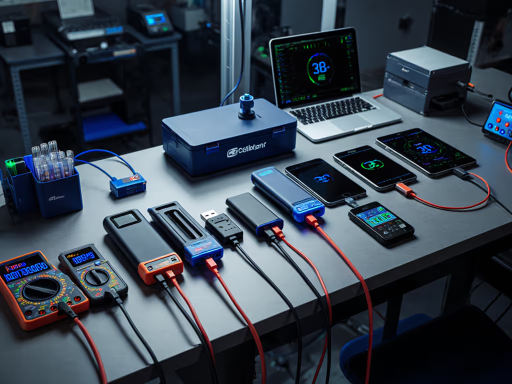
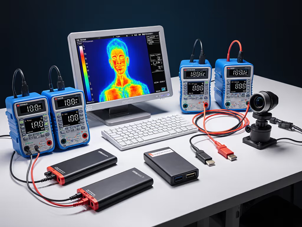
Multi-device power bank comparison is not about total watt-hours alone. It is about how the bank distributes current, maintains voltage stability, and negotiates protocol contracts under simultaneous load. Most reviews skip this because it requires inline logging with a USB-PD sniffer and thermal imaging across 30-minute cross-load cycles. Specs do not capture it. Marketing claims certainly do not. The trace does.
This guide unpacks the testing methods that expose real multi-device behavior, the architecture choices that enable stable simultaneous charging, and how to match a bank's distribution profile to your device ecosystem.
Before testing simultaneous charging, a proper multi-device comparison establishes the usable capacity of each port independently. For USB-A ports, this involves connecting the bank to a DC electronic load reference instrument set to draw the maximum supported current, logging the output voltage and current over the entire discharge cycle. For USB-C ports, capacity is verified by charging a test smartphone to 80% repeatedly until the bank exhausts, then multiplying the number of full or partial charges by the phone's 80%-capacity value.
Why 80%? Charging to full is thermally stressful and skews real-world metrics. A user rarely takes a device from 0% to 100% in a single bank session.
Once single-port capacity is measured in watt-hours (Wh), not the often-inflated milliampere-hour (mAh) spec, the true starting point becomes clear. Here is the disconnect: a 25,000 mAh bank sounds large but often delivers only 60-70% of that when measured in real Wh, due to voltage step-up conversion losses (typically a 10-20% energy penalty when boosting from internal 3.7V cells to 5V output).
Choice's methodology, adapted by rigorous labs, measures multi-device performance by charging two or more devices simultaneously and observing how much the charging speed drops relative to the single-port baseline. Higher-scoring banks show only minor power loss when two ports are active; cheaper banks suffer dramatic collapses in charging speed or complete port deactivation when a second device is added.
The test duration matters. Thirty minutes of sustained cross-load reveals thermal throttling that a 5-minute snapshot would miss.
A USB-C laptop negotiates a 20V/3.25A contract (65W) with the bank at startup. That handshake is delicate. If a second USB-C port begins drawing current at the same time (say a second laptop or a high-power phone charger connected inline), the bank's voltage rail can sag below 5.1V, the minimum threshold required to maintain USB PD negotiation. The laptop's device controller sees the brownout and drops the contract to 5V/2A (10W). The user notices: no visible indicator, just slower charging. The bank could not sustain dual high-power ports.
This failure is invisible without USB-PD trace capture. Voltage ripple measurement during protocol switching exposes whether the bank's power distribution firmware prioritizes the first-negotiated port or distributes current fairly. For an engineering-level look at voltage stability, thermal regulation, and firmware behavior, see our battery management system comparison.
Different architectures yield different behaviors.
Sequential logic (the cheapest approach): The bank charges devices one after another. When the first port reaches a threshold (user-defined or hardcoded), power switches to the next port. This can frustrate users expecting simultaneous charging, but it is simple and avoids voltage sag.
Parallel current-sharing with active load-balancing (mid-to-premium tier): The bank monitors current draw on each port and distributes available power dynamically. If one port is idle, all current flows to the active port; when both are active, current is split. This requires active switching, current-sense resistors, and firmware intelligence. It works well if the firmware is stable, but firmware bugs can cause oscillation, and the bank ping-pongs between ports, degrading charging speed on both.
Voltage regulation per port (premium, automotive-grade): Each port has its own voltage regulator and current limiter. Simultaneous charging is deterministic: each port independently regulates its output voltage to 5.1V ± 0.1V, regardless of load on other ports. This is the gold standard for protocol stability. Laptops and high-speed devices benefit most from this approach because voltage dips are minimal, and PD contracts stay locked.
Which approach does your target bank use? The spec sheet will not say. Trace or it didn't happen. A USB-PD capture during two-laptop simultaneous charging will show either: stable 20V on both ports (per-port regulation), sagging voltage requiring re-negotiation (poor load-balancing), or sequential switching (no true simultaneous charging).

Banks implement logic to avoid catastrophic failure. If a bank allocates current beyond its power budget, the input protection circuit trips, and the entire bank shuts down, a hard brownout that can corrupt an open file on a laptop.
Some banks disable the USB-A ports when USB-C PD is active at high wattage, prioritizing the USB-C path because it is more power-efficient (fewer conversion stages). Others reserve a small current budget (100-200 mA) for low-current ports (Bluetooth earbuds, smartwatches) to prevent auto-cutoff. A bank charging a handheld game console at 18W via USB-C and a phone via USB-A at 10W simultaneously creates a 28W total load. If the bank's maximum sustainable output is 25W and it is optimized for 20V USB-C, it may throttle the USB-A port to protect the higher-priority USB-C negotiation.
Undocumented priority rules are a major source of frustration. Choose a bank where the manual explicitly states: "USB-C port supports up to 65W PD + USB-A ports share up to 15W total when USB-C is active at >30W."
Discharge each port independently using a USB power meter or inline logging tool. Measure the total watt-hours delivered until the port cuts off. Compare advertised capacity to measured capacity. An efficiency of 70-90% is expected due to voltage conversion and internal resistance losses.
Example measurement:
Differences between ports reveal power distribution design. If USB-C delivers significantly more Wh than USB-A from the same internal cells, the bank wastes energy stepping down from USB-C to USB-A, indicating a poor topology.
Simultaneously charge two representative devices at typical speeds (e.g., a MacBook via USB-C PD at 60W and an iPhone via USB-A at 10W). Log voltage, current, and temperature every 10 seconds. Calculate the power delivered to each device over the 30-minute window.
Expected outcome for a high-quality bank:
Poor outcome (common in sub-$30 banks):
Capture USB-PD traffic (using a logic analyzer or inline sniffer) while charging a USB-C device and then connecting a second USB-C device. Does the bank renegotiate the first device's contract, or does it allocate power without re-negotiation? A stable bank will not drop the first device's voltage during the handshake for the second device.
Three techniques dominate third-party labs:
Capacity discharge test (DC load method): A Maynuo or equivalent electronic load draws a constant current (e.g., 2A) from the bank at room temperature (20-25 °C) until the bank can no longer deliver that current. Output voltage and current are logged continuously, and the data is graphed to show power decay over time. This gives the most accurate single-port capacity and reveals when a bank's output voltage drops below minimum thresholds (4.75V for USB-A, 4.5V for USB-C under heavy load).
Charge-discharge cycle tracking: The tester measures the energy input to the bank (via a USB multimeter) and the energy output when the bank discharges into a device. The ratio of output to input is the round-trip efficiency. Multiple cycles (5-10) reveal whether efficiency degrades with age or temperature.
Voltage and current monitoring under real-world load: Plug in the actual devices you plan to use (phone, laptop, tablet) and log voltage/current on each port over extended sessions (1-3 hours). This exposes thermal throttling, protocol renegotiation, and auto-cutoff behavior that idealized lab tests might miss. Temperature monitoring during this phase is critical; a bank that works fine at 22 °C may fail at 35 °C or in direct sun.
Voltage collapse on secondary port: A bank outputs stable 20.5V on the primary USB-C port but, when a second device is plugged into the secondary USB-C port, the primary port's voltage sags to 19V and the laptop renegotiates to a lower power profile. Root cause: insufficient charge pumps or undersized output capacitors on the primary rail.
Thermal shutdown during cross-load: The bank works fine for the first 20 minutes, but temperature climbs past 55 °C and the firmware throttles all ports to 5V/500mA (emergency mode). This is intentional protection, but it is poorly communicated. Users assume the bank is broken, not thermal-protected.
Auto-cutoff on low-current devices: When charging an AirTag, smartwatch, or wireless earbud case simultaneously with a laptop, the bank's low-current port detects <100mA draw and cuts off, assuming the device is disconnected. The secondary device stops charging, and the user has to replug it. This is a firmware tuning issue; quality banks implement configurable low-current thresholds or an "always-on" mode.
USB-A port disabled at high USB-C power: The bank's firmware, seeing USB-C pulling 50W, disables USB-A entirely to avoid voltage sag. This is a safety feature, but users expect simultaneous charging. Transparent documentation prevents frustration.
Firmware oscillation: On rare occasions, poorly tuned load-balancing firmware causes the bank to rapidly switch current between ports, destabilizing both voltage rails. The laptop and phone both charge slowly and erratically. This is rare but unrecoverable without a firmware update.
Cold and heat both degrade multi-device capability. In cold (<10 °C), internal cell resistance rises, and the bank can no longer sustain dual high-power loads; voltage sag becomes more severe. In heat (>40 °C), thermal management kicks in, and the bank reduces current to each port to keep the battery below its safe thermal threshold.
Labs conducting rigorous comparisons test at 20-25 °C (controlled room temp) and separately at 10 °C and 35 °C to map derating curves. For quantified derating curves across chemistries, see our temperature performance analysis. A bank rated for 65W might deliver only 45W per port at 35 °C and 30W at 10 °C when charging simultaneously.
No mainstream review publishes this data. Most reviewers work at room temperature and assume performance is constant. In reality, a winter trip, an outdoor summer event, or even a bank left in direct sun changes the multi-device behavior profile entirely.
USB PD, USB PD 3.1 with EPR (Extended Power Range), PPS (Programmable Power Supply), Quick Charge, Oppo VOOC, and Samsung PPS are incompatible negotiation languages. To match protocols and avoid slow charging, use our PD vs QC power bank guide. A bank supporting only USB PD will not trigger Samsung's 45W PPS mode on a Galaxy phone, nor will it unlock the 140W capacity of a new MacBook Pro (which uses PD 3.1 EPR).
Multi-device scenarios often involve mixed ecosystems: a USB-C Android phone (PPS), an older iPad (USB PD 2.0), and a MacBook (USB PD 3.1 EPR). A bank must support all three to deliver optimal speed to all three simultaneously. Cheaper banks support only USB PD 2.0, and newer devices will negotiate down to lower power profiles.
If the bank doesn't support your device's native protocol, you lose 50-70% of charging speed, even if the bank has enough total watts.
Verify protocol support by consulting the bank's manual, searching for teardown reviews that name the primary IC (power management chip), or contacting the manufacturer directly. Marketing copy will claim "supports USB PD," but will omit whether that is 2.0, 3.0, or 3.1.
Suppose you're a field photographer on a 14-hour shoot with a MacBook Pro 14" (PD 3.1 EPR 100W), a mirrorless camera (USB-C PD 65W), and an iPhone 15 Pro (USB-C PD 27W). All three devices are semi-discharged at hour 8. You want simultaneous charging during lunch (90 minutes) to maximize on-site productivity.
A tested multi-device power bank comparison reveals:
A 100 Wh measured-usable bank (typical 20,000 mAh model with ~75% efficiency) will deliver only 90 Wh in a full discharge from 100% to 0%. Your 90-minute simultaneous charge draws 135 Wh, so you will exhaust the bank before all three devices are full. You need either a 150 Wh bank (larger, heavier) or a second bank.
But here is the invisible detail: if the bank's per-port regulation is poor and voltage sags during simultaneous load, the iPhone might drop to 5W (instead of 12W), and the camera might drop to 8W (instead of 18W). Your total delivery plummets to 70W, and the 90 Wh bank drains faster. The specs looked sufficient, but the distribution architecture betrayed you. Testing exposes this.
Do not rely on the bank's built-in display alone; it is often wildly inaccurate. Pair a USB power meter (inline between bank and device) to log actual watts delivered. Many banks claim to display 65W while metering reveals only 35W due to cable losses or negotiation failures.
For the deepest confidence, capture a USB-PD trace during your first high-stakes charge session. A USB-C sniffer (available as a hat on Raspberry Pi or a standalone logic analyzer around $50) records every protocol message. You can then extract:
If the Request says 20V/3A and the bank complies, the contract is locked. If the bank drops to 5V/2A mid-session, the log shows the exact timestamp. This is forensic-level verification, and it is the only way to guarantee a bank truly supports your device's intended charging mode.
Start by defining your multi-device scenario: which devices, what chargers, typical simultaneous load, and climate. Then:
The banks that earn trust are those where the measured performance aligns with the advertised specs, and the multi-device behavior is transparent, not hidden in vague marketing claims. Demand the trace, not the promise. That is the only way to eliminate surprises when your entire workflow depends on simultaneous power delivery.